企业内网单向访问的实现——HUAWEI FW旁挂的配置
企业内网中常有这样的需求,管理员或老板希望能够访问其他业务部门主机的共享资料等信息,却不希望任何人访问管理员的共享信息。
以前我们介绍过通过利用ACL结合过滤策略来实现,见 《企业内网单向访问的实现—TCP三次握手的深入理解与应用》
和利用虚拟防火墙安全策略来实现,见《企业内网单向访问的实现—华为虚拟防火墙应用》
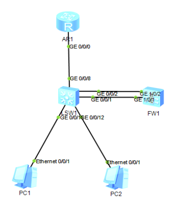
对于上面介绍的方法,有朋友提出如何在不改变现有拓扑的情况下,通过旁挂防火墙来控制内网主机的互访。下面我们就通过一个例子来进行介绍。
注:实现问题解决有多种方法,这里不做优劣比较,只是技术方法实现,实际工作中具体情况具体分析,适合的方法才是最好的方法。

实验拓扑说明:
AR1模拟外网设备
PC1 PC2模拟内网设备 地址 192.168.1.1/24 192.168.2.1/24
SW1模拟核心交换机 配置VLAN10 20 作为PC1 和PC2 的网关
在没有FW设备的情况下,配置基础设置,实现网络互通。
FW作为增加的安全设备,旁挂在SW1 上对VLAN间数据进行管理。
基础配置:
AR1
sysname R1
interface GigabitEthe.NET0/0/0
ip address 12.0.0.1 255.255.255.0
ip route-static 192.168.0.0 255.255.0.0 12.0.0.2
核心交换机SW1配置
sysname SW1
vlan batch 10 20 100
interface Vlanif10
ip address 192.168.1.254 255.255.255.0
interface Vlanif20
ip address 192.168.2.254 255.255.255.0
interface Vlanif100
ip address 12.0.0.2 255.255.255.0
interface GigabitEthernet0/0/8
port link-type access
port default vlan 100
interface GigabitEthernet0/0/11
port link-type access
port default vlan 10
interface GigabitEthernet0/0/12
port link-type access
port default vlan 20
PC1PC2配置相应IP地址,完成后测试PC互通正常,访问外网正常。


下面我们把防火墙旁挂在核心交换机上,对流量进行管控。
SW1增加接口配置
vlan batch 40 50
interface Vlanif40
ip address 10.1.1.1 255.255.255.0
interface Vlanif50
ip address 10.2.2.1 255.255.255.0
interface GigabitEthernet0/0/1
port link-type access
port default vlan 40
interface GigabitEthernet0/0/2
port link-type access
port default vlan 50
//增加与防火墙互联接口的配置
acl number 3000
rule 5 permit ip source 192.168.1.0 0.0.0.255 destination 192.168.2.0 0.0.0.255
traffic classifier 10to20
if-match acl 3000
traffic behavior 10to20
redirect ip-nexthop 10.1.1.2
traffic policy 10to20
classifier 10to20 behavior 10to20
interface GigabitEthernet0/0/11
traffic-policy 10to20 inbound
acl number 3001
rule 5 permit ip source 192.168.2.0 0.0.0.255 destination 192.168.1.0 0.0.0.255
traffic classifier 20to10
if-match acl 3001
traffic behavior 20to10
redirect ip-nexthop 10.2.2.2
traffic policy 20to10
classifier 20to10 behavior 20to10
interface GigabitEthernet0/0/12
traffic-policy 20to10 inbound
//分别将PC1访问PC2 和PC2访问PC1的流量引导到旁挂的防火墙上
ospf 100
area 0.0.0.0
network 192.168.1.0 0.0.0.255
network 10.1.1.1 0.0.0.0
ospf 200
area 0.0.0.0
network 192.168.2.0 0.0.0.255
network 10.2.2.1 0.0.0.0
//配置两个OSPF进程,分别用于引导出入防火墙的流量
防火墙配置
sysname FW1
interface GigabitEthernet1/0/1
ip address 10.1.1.2 255.255.255.0
#
interface GigabitEthernet1/0/2
ip address 10.2.2.2 255.255.255.0
firewall zone name v10
set priority 10
add interface GigabitEthernet1/0/1
firewall zone name v20
set priority 15
add interface GigabitEthernet1/0/2
//配置与核心交换机互联的接口和自定义区域中
ospf 100
area 0.0.0.0
network 10.1.1.2 0.0.0.0
#
ospf 200
area 0.0.0.0
network 10.2.2.2 0.0.0.0
//配置两个OSPF进程对应交换机流量的出入方向
security-policy
rule name 10to20
source-zone v10
destination-zone v20
source-address 192.168.1.0 mask 255.255.255.0
destination-address 192.168.2.0 mask 255.255.255.0
action deny
rule name 20to10
source-zone v20
destination-zone v10
source-address 192.168.2.0 0.0.0.255
destination-address 192.168.1.0 0.0.0.255
action permit
//配置安全策略,阻止PC1访问PC2,放行PC2访问PC1
配置完成后,检查结果PC1无法访问PC2 ,PC2正常访问PC1,两PC访问外网正常,达到了控制的目的。


注:同样的原理可以用引导其他流量至防火墙处理,如访问互联网流量,加强内网的安全性。


